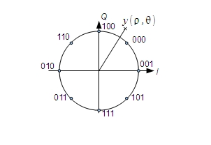


This figure represents the 8-PSK modulation with the binary mapping of bit b2b1b0

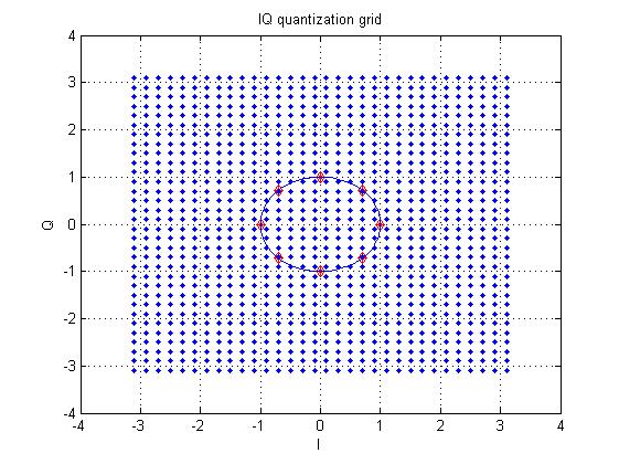
This figure represents the classical quantization grid (I and Q are quantized on 5 bits).
This figure represents the proposed polar quantization grid (rau and theta are also quantized on 5 bits).
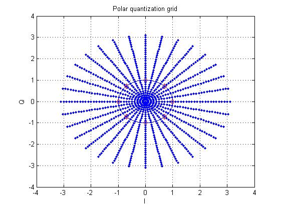
(The matlab file to generate the two previous figures is available here)
This figure represents the evolution of the LLRs of the 3 bits for a fix variance of the noise, rau constant and theta varying.
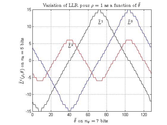
This figure represents the evolution of the LLR of b0 for a fix variance of the noise, different values of rau, and theta varying.
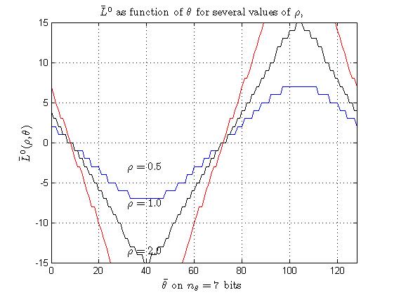
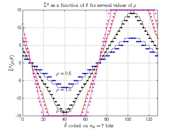
Based on the two last figures, one can see that the LLR can be approximated by a linear function of rau and theta.
The following figures show the approximation between the simplied method based on linear approximation and the optimal method. The parameters are R=6 and alpha = 0.046 (see the give matlab function and the related papers).
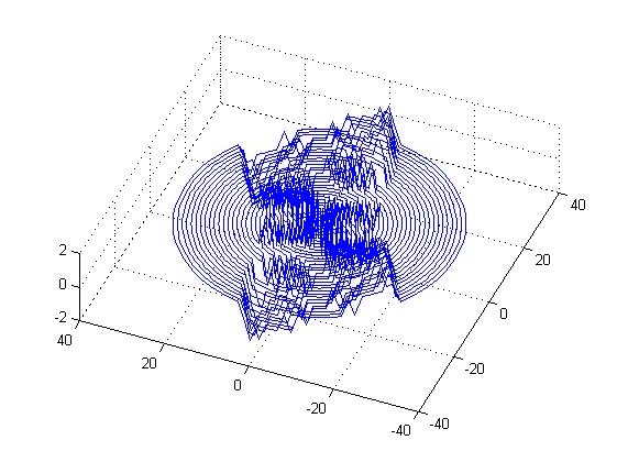
This figure shows, in a 3D view, the error (always bounded by 1) between the exact value of the LLR and the one obtained thanks to a simple linear interpolation. The x and y axis give the position of the quantized point and the z-axis show the quantization errror.
The matlab file to generate the four last previous figures is available here
To generate the same figures, type [llr0 llr1 llr2 llr0q llr1q llr2q] = Linear_interpolation_LLR(6,0.046) on matlab)

Return to main page of Emmanuel Boutillon